


LCD (Liquid Crystal Display) : LCD screen is an electronic display module and find a wide range of
applications. A 16x2 LCD display is very basic module and is very commonly used
in various devices and circuits. These modules are preferred over seven segment and other multi segment LED's. The reasons being: LCDs are
economical; easily programmable; have no limitation of displaying special &
even custom character (unlike in seven segments), animation and so on. A 16x2 LCD means it
can display 16 characters per line and there are 2 such lines. In this LCD each
character is displayed in 5x7 pixel matrix. This LCD has two registers, namely,
Command and Data.
The command register
stores the command instructions given to the LCD. A command is an instruction
given to LCD to do a predefined task like initializing it, clearing its screen,
setting the cursor position, controlling display etc. The data register stores
the data to be displayed on the LCD. The data is the ASCII value of the
character to be displayed on the LCD. Click to learn more about internal
structure of a LCD.
Block Diagram of LCD:
LCD stands for liquid
crystal display. They come in many sizes 8x1 , 8x2 ,10x2, 16x1 , 16x2 , 16x4 ,
20x2 , 20x4 ,24x2 , 30x2 , 32x2 , 40x2 etc . Many multinational companies
like Philips Hitachi Panasonic make their own special kind
of lcd's to be used in their products. All the lcd’s performs the same functions
(display characters numbers special characters ASCII characters
etc).Their programming is also same and they all have same 14 pins (0-13)
or 16 pins (0 to 15).
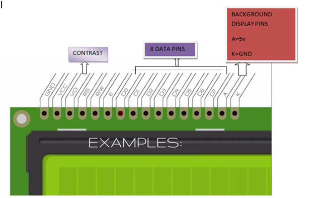
ALL LCDs have
- Eight(8)
Data pins
- VCC
(Apply 5v here)
- GND
(Ground this pin)
- RS
(Register select)
- RW
(read - write)
- EN
(Enable)
- V0
(Set Lcd contrast)
8-Data pins carries 8-bit data or
command from an external unit such as microcontroller.

Lcd have two registers:
1) Command
Register
2) Data Register
- Command Register:
When we send commands to lcd these commands go to Command register and
are processed their. Commands with their full description are given in the
picture below.
When RS=0 Command Register is Selected.
- Data Register: When we send Data to lcd it goes to data register and is processed their.
When RS=1 Data Register is selected.
Pin
diagram of LCD:
Pin description:
| Pin No: | Name | Function |
| 1 | VSS | This pin must be connected to the ground |
| 2 | VCC | Positive supply voltage pin (5V DC) |
| 3 | VEE | Contrast adjustment |
| 4 | RS | Register selection |
| 5 | R/W | Read or write |
| 6 | E | Enable |
| 7 | DB0 | Data |
| 8 | DB1 | Data |
| 9 | DB2 | Data |
| 10 | DB3 | Data |
| 11 | DB4 | Data |
| 12 | DB5 | Data |
| 13 | DB6 | Data |
| 14 | DB7 | Data |
| 15 | LED+ | Back light LED+ |
| 16 | LED- | Back light LED- |
16×2 LCD module commands:
16×2 LCD module has a set of preset command instructions. Each
command will make the module to do a particular task. These commands are very important for
displaying data in LCD. The list of commands given below:
Command
|
Function
|
0F
|
For switching on
LCD, blinking the cursor.
|
1
|
Clearing the
screen
|
2
|
Return home.
|
4
|
Decrement cursor
|
6
|
Increment cursor
|
E
|
Display on and
also cursor on
|
80
|
Force cursor to
beginning of the first line
|
C0
|
Force cursor to
beginning of second line
|
38
|
Use two lines and
5x7 matrix
|
83
|
Cursor line 1
position 3
|
3C
|
Activate second
line
|
0C3
|
Jump to second
line position 3
|
0C1
|
Jump to second
line position1
|
LCD initialization:
The steps that has to be done for
initializing the LCD display is given below and these steps are common for
almost all applications.
§ Send 38H to the 8
bit data line for initialization
§ Send 0FH for making
LCD ON, cursor ON and cursor blinking ON.
§ Send 06H for
incrementing cursor position.
§ Send 01H for
clearing the display and return the cursor.
Sending data to the LCD:
The steps for sending data to the LCD
module is given below. I have already said that the LCD module has pins namely
RS, R/W and E. It is the logic state of these pins that make the module to
determine whether a given data input is a command or data to be
displayed.
- Make R/W low.
- Make RS=0 if data
byte is a command and make RS=1 if the data byte is a data to be displayed.
- Place data byte on
the data register.
- Pulse E from high
to low.
- Repeat above steps
for sending another data.


Interfacing of LCD
with 8051:
1)
Display Welcome
to all on the 1st line:
a) Circuit:
b) Code
· ASM Code:
$mod51
org 00h
back:
mov A,#01h
acall command
mov a,#06h
acall command
mov a,#38h
acall command
mov a,#0eh
acall command
mov a,#80h
acall command
mov A,#'C'
acall display
mov A,#'E'
acall display
mov A,#'T'
acall display
mov A,#'P'
acall display
mov A,#'A'
acall display
mov A,#' '
acall display
mov A,#'I'
acall display
mov A,#'N'
acall display
mov A,#'F'
acall display
mov A,#'0'
acall display
mov A,#'T'
acall display
mov A,#'E'
acall display
mov A,#'C'
acall display
mov A,#'H'
acall display
SJMP back
command:
mov P1,A
Clr P3.0
Clr P3.1
setb P3.2
Acall delay
clr P3.2
ret
display:
mov P1,A
setb P3.0
Clr P3.1
setb P3.2
Acall delay
clr P3.2
ret
delay:
mov R1,#100
L13: mov R2,#100
L12: mov R3,#50
L11: DJNZ R3,L11
DJNZ R2,L12
DJNZ R1,L13
ret
end
Alternate way :
$mod51
org 00h
rs equ p3.0
rw equ p3.1
en equ p3.2
lcd equ p1
mov a,#01h
acall command
mov a,#06h
acall command
mov a,#38h
acall command
mov a,#0eh
acall command
mov a,#80h
acall command
mov r0,#13
mov dptr,#L4
L1: clr a
movc a,@a+dptr
acall dATAA
inc dPTR
djnz r0,L1
command:
mov lcd,a
clr rs
clr rw
setb en
acall delay
clr en
ret
DATAA:
MOV LCD,A
SETB RS
CLR RW
SETB EN
ACALL DELAY
CLR EN
RET
delay:
mov r2,#255
o: mov r3,#255
n: mov r4,#10
m: djnz r4,m
djnz r3,n
djnz r2,o
ret
org 200h
L4:DB 'Welcome To all',0
END
· C Code:
#include<reg51.h>
sbit rs=P3^0;
sbit rw=P3^1;
sbit en=P3^2;
unsigned char arr1[]={0x0e,0x01,0x06,0x80,0x38};
unsigned char arr2[]={"Welcome To All"};
void command();
void display();
int j,k,l,m,n;
void delay()
{ int x,y;
for(x=0;x<=100;x++)
{
for(y=0;y<=1275;y++);
}
}
void main()
{
while(1)
{
for(j=0;j<5;j++)
{
P1=arr1[j];
command();
}
for(k=0;k<15;k++)
{
P1=arr2[k];
display();
}
}
}
void command()
{
rs=0;
rw=0;
en=1;
delay();
en=0;
}
void display()
{
rs=1;
rw=0;
en=1;
delay();
en=0;
}
c) Simulation
2)
Display Welcome
to all on the 1st line and God Bless You on the 2nd
line.
a)
Code
·
ASM Code
$mod51
org 00h
rs equ p3.0
rw equ p3.1
en equ p3.2
lcd equ p1
mov a,#01h
acall command
mov a,#06h
acall command
mov a,#38h
acall command
mov a,#0eh
acall command
mov a,#80h
acall command
mov r0,#13
mov dptr,#L4
L1: clr a
movc a,@a+dptr
acall dATAA
inc dPTR
djnz r0,L1
mov a,#0c0h
acall command
mov r1,#13
mov dptr,#L3
L2: clr a
movc a,@a+dptr
acall dATAA
inc dptr
djnz r1,L2
command:
mov lcd,a
clr rs
clr rw
setb en
acall delay
clr en
ret
DATAA:
MOV LCD,A
SETB RS
CLR RW
SETB EN
ACALL DELAY
CLR EN
RET
delay:
mov r2,#255
o: mov r3,#255
n: mov r4,#10
m: djnz r4,m
djnz r3,n
djnz r2,o
ret
org 200h
L4:DB 'Welcome to all ',0
L3:DB 'God Bless You ',0
END
·
C Code
#include<reg51.h>
sbit rs=P3^0;
sbit rw=P3^1;
sbit en=P3^2;
unsigned char arr1[]={0x0e,0x01,0x06,0x80,0x38};
unsigned char arr2[]={"Welcome To All"};
unsigned char arr3[]={"God Bless You "};
void command();
void display();
int j,k,l,m,n;
void delay()
{ int x,y;
for(x=0;x<=100;x++)
{
for(y=0;y<=1275;y++);
}
}
void main()
{
while(1)
{
for(j=0;j<5;j++)
{
P1=arr1[j];
command();
}
for(k=0;k<15;k++)
{
P1=arr2[k];
display();
}
P1=0xc0;
command();
for(k=0;k<15;k++)
{
P1=arr3[k];
display();
}
}
}
void command()
{
rs=0;
rw=0;
en=1;
delay();
en=0;
}
void display()
{
rs=1;
rw=0;
en=1;
delay();
en=0;
}
b)
Simulation

3)
Trafic Light
a)
ASM Code
$mod51
lcd equ
p1
rs equ
p3.3
rw equ
p3.2
en equ
p3.1
egr equ
p2.0
erd equ
p2.1
eyl equ
p2.2
wgr equ
p2.3
wrd equ
p2.4
wyl equ
p2.5
ngr equ
p0.0
nrd equ
p0.1
nyl equ
p0.2
sgr equ
p0.3
srd equ
p0.4
syl equ
p0.5
nsen equ
p3.7
ssen equ
p3.6
esen equ
p3.5
wsen equ
p3.4
org 0h
acall
lcd_ini
mov
dptr,#welcome
acall
hind
mov
a,#0c0h
acall cmd
mov
dptr,#welcome1
acall
hind
acall
delay1
mov
a,#01h
acall cmd
mov
dptr,#direction
acall
hind
mov
a,#0c0h
acall cmd
go:
mov
dptr,#northgo
acall
hind
clr ngr
clr wrd
clr srd
clr erd
acall
delay1
acall
delay1
acall
start
mov
dptr,#nerdy
acall
hind
setb erd
clr eyl
setb ngr
clr nyl
acall
delay2
acall
start
mov
dptr,#eastgo
acall
hind
setb nyl
clr nrd
setb eyl
clr egr
acall
delay1
acall
delay1
acall
start
mov
dptr,#esrdy
acall
hind
setb srd
clr syl
setb egr
clr eyl
acall
delay2
acall
start
mov
dptr,#southgo
acall
hind
setb syl
clr sgr
setb eyl
clr erd
acall
delay1
acall
delay1
acall
start
mov
dptr,#swrdy
acall
hind
setb sgr
setb wrd
clr syl
clr wyl
acall
delay2
acall
start
mov
dptr,#westgo
acall
hind
setb wyl
clr wgr
setb syl
clr srd
acall
delay1
acall
delay1
acall
start
mov
dptr,#wnrdy
acall
hind
setb wgr
clr wyl
setb nrd
clr nyl
acall
delay2
acall
start
setb wyl
setb nyl
ajmp go
delay1:
mov
r4,#07h
gh: mov
r5,#0ffh
ru: acall
delay
djnz r5,ru
djnz r4,gh
ret
delay2:
mov
r3,#04h
gj: mov
r2,#0ffh
eu: acall
delay
djnz r2,eu
djnz r3,gj
ret
start:
mov
a,#01h
acall cmd
mov
dptr,#direction
acall
hind
mov
a,#0c0h
acall cmd
ret
hind:
clr a
movc
a,@a+dptr
acall dat
inc dptr
jnz hind
ret
lcd_ini:
mov
a,#38h
acall cmd
mov
a,#01h
acall cmd
mov
a,#06h
acall cmd
mov
a,#0eh
acall cmd
mov
a,#80h
acall cmd
ret
delay:
mov
r6,#02h
yu: mov
r7,#0ffh
rt:
jnb
nsen,ngr1
jnb
wsen,wgr1
jnb
ssen,sgr1
jnb
esen,egr1
djnz
r7,rt
djnz
r6,yu
ret
ngr1:
acall
again
mov
p2,#0ffh
mov
p0,#0ffh
clr ngr
clr wrd
clr erd
clr srd
ii4: sjmp
ii4
wgr1:
acall
again
mov
p2,#0ffh
mov
p0,#0ffh
clr wgr
clr nrd
clr erd
clr srd
nh: sjmp
nh
sgr1:
acall
again
mov
p2,#0ffh
mov
p0,#0ffh
clr sgr
clr wrd
clr erd
clr nrd
ii: sjmp
ii
egr1:
acall
again
mov
p2,#0ffh
mov
p0,#0ffh
clr egr
clr wrd
clr nrd
clr srd
ii1: sjmp
ii1
again:
mov
a,#01h
acall cmd
mov
dptr,#emergency
acall
hind
ret
cmd:
mov lcd,a
clr rs
clr rw
setb en
acall
delay
clr en
ret
dat:
mov lcd,a
setb rs
clr rw
setb en
acall
delay
clr en
ret
welcome:
db 'Welcome to Smart',0
welcome1:
db 'Traffic Light Controller',0
direction:
db 'N E S
W ',0
northgo:
db 'GO
STP STP STP',0
southgo:
db 'STP STP GO STP',0
eastgo: db
'STP GO STP STP',0
westgo:
db 'STP STP STP GO ',0
nerdy:
db 'WaitRDY STP STP',0
esrdy: db 'STP WaitRDY STP',0
swrdy:
db 'STP STP WaitRDY',0
wnrdy:
db 'RDY STP STPWait',0
emergency:
db 'EMERGENCY Plz Wait',0
end


