Sunday 30 April 2017

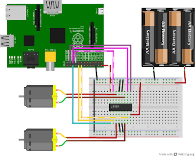
Interfacing of Raspberry pi with Motors:

Interfacing of Raspberry pi with Motors:

Now ready to write code to motor.  Turn on your Raspberry Pi and Open the terminal window.
1)   Write a program to Motor move Forward and Backward while switch is pressed.
Create a new text file “motor1.py” by typing the following:
Sudo nano motor1.py
After that write following code to the Text editer page:

import os
import RPi.GPIO as GPIO
from time import sleep
GPIO.setwarnings(False)
GPIO.setmode(GPIO.BOARD) #board usage gpio pin , bcm usasge pin mnumber
GPIO.setup(3,GPIO.IN)
GPIO.setup(4,GPIO.IN)
GPIO.setup(5,GPIO.OUT)
GPIO.setup(6,GPIO.OUT)
print(" interfacing of Switch and Motor")

while True:
    if( GPIO.input(3)== False):
        print("Switch is Pressed then motor move Forward")

            GPIO.output(5,GPIO.HIGH)
            GPIO.output(6,GPIO.LOW)

            sleep(1)
           
    elsif( GPIO.input(4)== False):
       print("Switch is Pressed then motor move Backward")
        GPIO.output(5,GPIO.LOW)
        GPIO.output(6,GPIO.HIGH)

        sleep(2)
       
After writing the code we checked it, save and exit the text editor with
 “Ctrl + x” then “y” then “enter”.
To Running this Code Type:

sudo python motor1.py
then
You will see the Motor moved Forward or Backward when we pressed the switch.
Circuit Diagram:


1)   Write a program for Moving Robot.
Create a new text file “motor2.py” by typing the following:
Sudo nano motor2.py
After that write following code to the Text editer page:

import os
import RPi.GPIO as GPIO
from time import sleep
GPIO.setwarnings(False)
GPIO.setmode(GPIO.BOARD) #board usage gpio pin , bcm usasge pin mnumber
GPIO.setup(1,GPIO.IN)
GPIO.setup(2,GPIO.IN)
GPIO.setup(3,GPIO.IN)
GPIO.setup(4,GPIO.IN)

GPIO.setup(5,GPIO.OUT)
GPIO.setup(6,GPIO.OUT)
GPIO.setup(7,GPIO.OUT)
GPIO.setup(8,GPIO.OUT)

print(" interfacing of Switch and Motor")

while True:
    if( GPIO.input(1)== False):
        print("Switch is Pressed then Motor move Forward")

            GPIO.output(5,GPIO.HIGH)
            GPIO.output(6,GPIO.LOW)
            GPIO.output(7,GPIO.HIGH)
            GPIO.output(8,GPIO.LOW)


            sleep(1)
           
    elsif( GPIO.input(2)== False):
       print("Switch is Pressed then Motor move Backward")
        GPIO.output(5,GPIO.LOW)
        GPIO.output(6,GPIO.HIGH)
            GPIO.output(5,GPIO.LOW)
            GPIO.output(6,GPIO.HIGH)


        sleep(2)
        elsif( GPIO.input(3)== False):
       print("Switch is Pressed the Motor move Left")
        GPIO.output(5,GPIO.HIGH)
        GPIO.output(6,GPIO.LOW)
            GPIO.output(5,GPIO.LOW)
            GPIO.output(6,GPIO.LOW)


        sleep(2)
elsif( GPIO.input(4)== False):
       print("Switch is Pressed then Motor move Right")
        GPIO.output(5,GPIO.LOW)
        GPIO.output(6,GPIO.LOW)
            GPIO.output(5,GPIO.HIGH)
            GPIO.output(6,GPIO.LOW)


        sleep(2)

After writing the code we checked it, save and exit the text editor with
 “Ctrl + x” then “y” then “enter”.
To Running this Code Type:

sudo python motor2.py
then
You will see Robot move when switch is pressed.

Circuit Diagram:


Saturday 29 April 2017

Interfacing of Lcd with Raspberry Pi:

LCD (Liquid Crystal Display):

 LCD screen is an electronic display module and find a wide range of applications. A 16x2 LCD display is very basic module and is very commonly used in various devices and circuits. These modules are preferred over seven segment and other multi segment LED's. The reasons being: LCDs are economical; easily programmable; have no limitation of displaying special & even custom character (unlike in seven segments), animation and so on. A 16x2 LCD means it can display 16 characters per line and there are 2 such lines. In this LCD each character is displayed in 5x7 pixel matrix. This LCD has two registers, namely, Command and Data.
                      The command register stores the command instructions given to the LCD. A command is an instruction given to LCD to do a predefined task like initializing it, clearing its screen, setting the cursor position, controlling display etc. The data register stores the data to be displayed on the LCD. The data is the ASCII value of the character to be displayed on the LCD. Click to learn more about internal structure of a LCD.
           
Block Diagram of LCD:

LCD stands for liquid crystal display. They come in many sizes 8x1 , 8x2 ,10x2, 16x1 , 16x2 , 16x4 , 20x2 , 20x4 ,24x2 , 30x2 , 32x2 , 40x2 etc . Many multinational companies like Philips Hitachi Panasonic make their own special kind of lcd's to be used in their products. All the lcd’s performs the same functions (display characters numbers special characters ASCII characters etc).Their programming is also same and they all have same 14 pins (0-13) or 16 pins (0 to 15). 

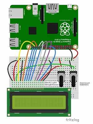
  The wiring for the LCD is as follows:
 1 : GND
 2 : 5V
 3 : Contrast (0-5V)
 4 : RS (Register Select)
 5 : R/W (Read Write)       - GROUND THIS PIN
 6 : Enable or Strobe
 7 : Data Bit 0            
 8 : Data Bit 1            
 9 : Data Bit 2            
 10: Data Bit 3            
 11: Data Bit 4
 12: Data Bit 5
 13: Data Bit 6
 14: Data Bit 7
 15: LCD Backlight +5V
16: LCD Backlight GND


Interfacing of Lcd with Raspberry Pi:

1) Write a program to Display “ABCDEFG” on the Lcd using 8 Bit Mode:

Now ready to write code to Display on LCD.  Turn on your Raspberry Pi and Open the terminal window.
Create a new text file “lcd1.py” by typing the following:
Sudo nano lcd1.py

After that write following code to the Text editer page: 

import RPi.GPIO as IO          
import time                            
import sys
IO.setmode (IO.BCM #board usage gpio pin , bcm usasge pin mnumber IO.setup(6,IO.OUT)                # initialize all 10  GPIO Pins as a outputs
IO.setup(22,IO.OUT)
IO.setup(21,IO.OUT)
IO.setup(20,IO.OUT)
IO.setup(16,IO.OUT)
IO.setup(12,IO.OUT)
IO.setup(25,IO.OUT)
IO.setup(24,IO.OUT)
IO.setup(23,IO.OUT)
IO.setup(18,IO.OUT)
def send_a_command (command):              
    pin=command
    PORT(pin);                                                
    IO.output(6,0)                     #put rs=0; means lcd work in command mode                    
    IO.output(22,1)         # first put the value of en pin is 1 then
    time.sleep(0.05)  # after some delay put zero
    IO.output(22,0)                                        
    pin=0
    PORT(pin);                                              
def send_a_character (character):              
    pin=character
    PORT(pin);
    IO.output(6,1)   #  put rs=1; means lcd work in data mode
    IO.output(22,1) ) # first put the value of en pin is 1 then
    time.sleep(0.05) # after some delay put zero
    IO.output(22,0)
    pin=0
    PORT(pin);
def PORT(pin):                    # assig PIN by taking PORT value
    if(pin&0x01 == 0x01):
        IO.output(21,1)             # if  bit0 of 8bit 'pin' is true, pull PIN21 high
    else:
        IO.output(21,0)            # if  bit0 of 8bit 'pin' is false, pull PIN21 low
    if(pin&0x02 == 0x02):
        IO.output(20,1)           # if  bit1 of 8bit 'pin' is true, pull PIN20 high
    else:
        IO.output(20,0)       #  if  bit1 of 8bit 'pin' is false, pull PIN20 low            
    if(pin&0x04 == 0x04):
        IO.output(16,1)  # if  bit2 of 8bit 'pin' is true, pull PIN16 high
    else:
        IO.output(16,0)     # if  bit2 of 8bit 'pin' is false, pull PIN16 low
    if(pin&0x08 == 0x08):
        IO.output(12,1) # if  bit3 of 8bit 'pin' is true, pull PIN12 high
    else:
        IO.output(12,0)   # if  bit3 of 8bit 'pin' is false, pull PIN12 low
if(pin&0x10 == 0x10):
        IO.output(25,1)  # if  bit4 of 8bit 'pin' is true, pull PIN25 high
    else:
        IO.output(25,0) # if  bit4 of 8bit 'pin' is false, pull PIN25 low
    if(pin&0x20 == 0x20):
        IO.output(24,1)  # if  bit5 of 8bit 'pin' is true, pull PIN24 high
    else:
        IO.output(24,0)  # if  bit5 of 8bit 'pin' is false, pull PIN24 low
    if(pin&0x40 == 0x40):
        IO.output(23,1)  # if  bit6 of 8bit 'pin' is true, pull PIN23 high
    else:
        IO.output(23,0)  # if  bit6 of 8bit 'pin' is false, pull PIN23 low
    if(pin&0x80 == 0x80):
        IO.output(18,1)   # if  bit7 of 8bit 'pin' is true, pull PIN18 high                    
    else:
        IO.output(18,0)     # if  bit7 of 8bit 'pin' is false, pull PIN18 low                
       
while 1:  
    send_a_command(0x01);                    # CLEAR DISPLAY SCREEN
    send_a_command(0x38);                    # INITIALIZE 16*2 line LCD
    send_a_command(0x0E);                    # DISPLAY ON CURSOR BLINKING
    send_a_character(0x41);                    # ASCII code for 'A'
    send_a_character(0x42);                    # ASCII code for 'B'
    send_a_character(0x43);                    # ASCII code for 'C'
    send_a_character(0x44);                    # ASCII code for 'D'
    send_a_character(0x45);                    # ASCII code for 'E'
    send_a_character(0x46);                    # ASCII code for 'F'
    send_a_character(0x47);                    # ASCII code for 'G'
    time.sleep(1)

After writing the code we checked it, save and exit the text editor with
 “Ctrl + x” then “y” then “enter”.
To Running this Code Type:

sudo python lcd1.py
then

You will see the ABCDEFG is Display on the LCD.

Circuit Diagram:


Interfacing of Raspberry pi with Led and Sensors

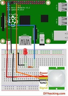
Interfacing of Raspberry pi with led and Sensors:

Now ready to write code to sensor and Led.  Turn on your Raspberry Pi and Open the terminal window.
Create a new text file “sensor1.py” by typing the following:
Sudo nano sensor1.py
After that write following code to the Text editer page:

import os
import RPi.GPIO as GPIO
from time import sleep
GPIO.setwarnings(False)
GPIO.setmode(GPIO.BOARD) #board usage gpio pin , bcm usasge pin mnumber
GPIO.setup(3,GPIO.IN)
GPIO.setup(5,GPIO.OUT)
print(" interfacing of Sensor and Led")

while True:
    if( GPIO.input(3)== False):
        print("Sensor is activate")

            GPIO.output(5,GPIO.HIGH)
            sleep(1)
           
    else:
        GPIO.output(5,GPIO.LOW)
            sleep(1)
        sleep(2)
       
After writing the code we checked it, save and exit the text editor with
 “Ctrl + x” then “y” then “enter”.
To Running this Code Type:

sudo python sensor1.py
then
You will see the LED turn on when sensor is activate.

Circuit Diagram:


Interfacing of Raspberry pi with led and Switch

Interfacing of Raspberry pi with led and Switch:

Now ready to write code to switch and Led.  Turn on your Raspberry Pi and Open the terminal window.
Create a new text file “switch1.py” by typing the following:
Sudo nano switch1.py
After that write following code to the Text editer page:

import os
import RPi.GPIO as GPIO
from time import sleep
GPIO.setwarnings(False)
GPIO.setmode(GPIO.BOARD) #board usage gpio pin , bcm usasge pin mnumber
GPIO.setup(3,GPIO.IN)
GPIO.setup(5,GPIO.OUT)
print(" interfacing of Switch and Led")

while True:
    if( GPIO.input(3)== False):
        print("Switch is Pressed")

            GPIO.output(5,GPIO.HIGH)
            sleep(1)
           
    else:
        GPIO.output(5,GPIO.LOW)
            sleep(1)
        sleep(2)
       
After writing the code we checked it, save and exit the text editor with
 “Ctrl + x” then “y” then “enter”.
To Running this Code Type:

sudo python switch1.py
then
You will see the LED turn on when switch is pressed.

Circuit Diagram: