


Serial Communication:

BASICS OF SERIAL COMMUNICATION:
· serial
communication uses single data line making it much cheaper
·
enables
two computers in different cities to communicate over the telephone
·
byte
of data must be converted to serial bits using a parallel-in-serial-out shift
register and transmitted over a single data line
·
receiving
end there must be a serial-in-parallel-out shift register
·
if
transferred on the telephone line, it must be converted to audio tones by modem
·
for
short distance the signal can be transferred using wire
·
how
PC keyboards transfer data to the motherboard
·
2
methods, asynchronous and synchronous
·
synchronous method transfers a block of data (characters) at a
time
·
asynchronous method transfers a single byte at a time
·
Uses
special IC chips called UART (universal asynchronous receiver-transmitter) and
USART (universal synchronous asynchronous receiver-transmitter)
·
8051
chip has a built-in UART

·
Half- and full-duplex transmission
·
if
the data can be transmitted and received, it is a duplex transmission
·
simplex transmissions the computer only sends data
·
duplex
transmissions can be half or full duplex
·
depends
on whether or not the data transfer can be simultaneous
·
If
one way at a time, it is half duplex
·
If
can go both ways at the same time, it is full duplex
·
full
duplex requires two wire conductors for the data lines (in addition to the
signal ground)
·
Asynchronous
serial communication and data framing
·
data coming in 0s and 1s
·
to make sense of the data sender and receiver agree
on a set of rules
·
Protocol
·
how the data is packed
·
how many bits/character
·
when the data begins and ends
·
Start
and stop bits
·
asynchronous method, each character is placed
between start and stop bits
·
called framing
·
start bit is always one bit
·
stop bit can be one or two bits
·
start bit is always a 0 (low)
·
stop bit(s) is 1 (high)
·
LSB is sent out first

·
in modern PCs one stop bit is standard
·
when transferring a text file of ASCII characters
using 1 stop bit there is total of 10 bits for each character
·
8 bits for the ASCII code (1 parity bit), 1 bit each
for the start and stop bits
·
for each 8-bit character there are an extra 2 bits,
which gives 20% overhead
·
Data
transfer rate
·
rate of data transfer bps (bits per second)
·
widely used terminology for bps is baud rate
·
baud and bps rates are not necessarily equal
·
baud rate is defined as the number of signal changes
per second
·
RS232
standards
·
most widely used serial I/O interfacing standard
·
input and output voltage levels are not TTL
compatible
·
1 bit is represented by -3 to -25 V
·
0 bit is +3 to +25 V
·
-3 to +3 is undefined
·
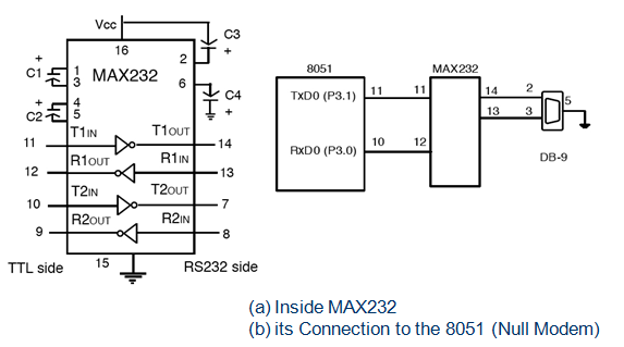
to connect RS232 to a microcontroller system must
use voltage converters such as MAX232 to convert the TTL logic levels to the
RS232 voltage levels, and vice versa
·
MAX232 IC chips are commonly referred to as line
drivers

·

Data communication classification
Data communication classification
·
DTE (data terminal equipment)
·
DCE (data communication equipment)
·
DTE - terminals and computers that send and receive
data
·
DCE - communication equipment responsible for
transferring the data
·
simplest connection between a PC and microcontroller
requires a minimum of three pins, TxD, RxD, and ground

·
Examining
RS232 handshaking signals
·
many of the pins of the RS-232 connector are used
for handshaking signals
·
they are not supported by the 8051 UART chip
·
PC/compatible
COM ports
·
PC/compatible computers (Pentium) microprocessors
normally have two COM ports
·
both ports have RS232-type connectors
·
COM ports are designated as COM 1 and COM 2 (replaced
by USB ports)
·
can connect the 8051 serial port to the COM 2 port
8051 CONNECTION TO RS232:
·
RxD
and TxD pins in the 8051
·
8051 has two pins used for transferring and
receiving data serially
·
TxD and RxD are part of the port 3 group
·
pin 11 (P3.1) is assigned to TxD
·
pin 10 (P3.0) is designated as RxD
·
these pins are TTL compatible
·
require a line driver to make them RS232 compatible
·
driver is the MAX232 chip
·
MAX232
·
converts from RS232 voltage levels to TTL voltage
levels
·
uses a +5 V power source
·
MAX232 has two sets of line drivers for transferring
and receiving data
·
line drivers used for TxD are called T1 and T2
·
line drivers for RxD are designated as R1 and R2
·
T1 and R1 are used together for TxD and RxD of the
8051
·
second set is left unused
·
MAX233
·
MAX233 performs the same job as the MAX232
·
eliminates the need for capacitors
·
much more expensive than the MAX232

8051 SERIAL PORT PROGRAMMING IN ASSEMBLY:
·
Baud
rate in the 8051
·
serial communications of the 8051 with the COM port
of the PC
·
must make sure that the baud rate of the 8051 system
matches the baud rate of the PC's COM port
·
can use Windows HyperTerminal program

·
Baud
rate in the 8051
·
baud rate in the 8051 is programmable
·
done with the help of Timer 1
·
relationship between the crystal frequency and the
baud rate in the 8051
·
8051 divides the crystal frequency by 12 to get the
machine cycle frequency
·
XTAL = 11.0592 MHz, the machine cycle frequency is
921.6 kHz
·
8051's UART divides the machine cycle frequency of
921.6 kHz by 32 once more before it is used by Timer 1 to set the baud rate
·
921.6 kHz divided by 32 gives 28,800 Hz
·
Timer 1 must be programmed in mode 2, that is 8-bit,
auto-reload

Ex-1 (a):
With XTAL = 11.0592 MHz, find the TH1 value needed to have the following baud rates. (a) 9600 (b) 2400 (c) 1200
With XTAL = 11.0592 MHz, find the TH1 value needed to have the following baud rates. (a) 9600 (b) 2400 (c) 1200
·
machine cycle frequency
= 11.0592 MHz / 12 = 921.6 kHz
·
Timer 1 frequency provided by 8051 UART
= 921.6 kHz / 32 = 28,800 Hz
(a) 28,800 / 3 = 9600 where -3 = FD (hex)
(b) 28,800 / 12 = 2400 where -12 = F4 (hex)
(c) 28,800 / 24 = 1200 where -24 = E8 (hex)
·
SBUF (serial buffer) register
·
a byte of data to be transferred via the TxD line
must be placed in the SBUF register
·
SBUF holds the byte of data when it is received by
the RxD line
·
can be accessed like any other register
MOV
SBUF,#'D' ;load SBUF=44H, ASCII for 'D‘
MOV
SBUF,A ;copy accumulator
into SBUF
MOV
A,SBUF ;copy SBUF into
accumulator
·
when a byte is written, it is framed with the start
and stop bits and transferred serially via the TxD pin
·
when the bits are received serially via RxD, it is
deframe by eliminating the stop and start bits, making a byte out of the data
received, and then placing it in the SBUF
·
SCON (serial control) register
·
to program the start bit, stop bit, and data bits

·
SM0
and SM1 determine the mode
·
only
mode 1 is important
·
when
mode 1 is chosen, the data framing is 8 bits, 1 stop bit, and 1 start bit
·
compatible
with the COM port of PCs
·
mode
1 allows the baud rate to be variable and is set by Timer 1 of the 8051
·
for
each character a total of 10 bits are transferred, where the first bit is the
start bit, followed by 8 bits of data, and finally 1 stop bit.
·
REN
(receive enable)
·
REN=1,
allows 8051 to receive data on the RxD
·
if
8051 is to both transfer and receive data, REN must be set to 1
·
REN=0,
the receiver is disabled
·
SETB
SCON.4 and CLR SCON.4,
·
TI
(transmit interrupt)
·
when
8051 finishes the transfer of the 8-bit character, it raises the TI flag to
indicate that it is ready to transfer another byte
·
RI
(receive interrupt)
·
when
the 8051 receives data serially via RxD, it places the byte in the SBUF
register
·
then
raises the RI flag bit to indicate that a byte has been received and should be
picked up before it is lost
·
Program to transfer data serially
·
TMOD register is loaded with the value 20H
·
TH1 is loaded with value to set the baud rate
·
SCON register is loaded with the value 50H
·
TR1 is set to 1 to start Timer1
·
TI is cleared by the "CLR TI" instruction
·
transmit character byte is written into the SBUF
register
·
TI flag bit is monitored to see if the character has
been transferred completely.
Serial Data Transmission Procedure:


Serial Data Transmission Procedure:


Ex1(b):
Write a program to transfer letter "A" serially at 4800 baud, continuously.
Write a program to transfer letter "A" serially at 4800 baud, continuously.
#include<reg51.h>
unsigned char i;
int j;
void main()
{
while(1)
{
TMOD=0X20;
SCON=0X50;
TH1=0XFD;
TR1=1;
SBUF=A;
while(TI==0);
TR1=0;
TI=0;
}
}

Ex 1(c):
Write a program to transfer the message "Hello" serially at 9600 baud, 8-bit data, 1 stop bit. Do this continuously.
Write a program to transfer the message "Hello" serially at 9600 baud, 8-bit data, 1 stop bit. Do this continuously.
#include<reg51.h>
unsigned char i;
int j;
unsigned char
arr[]={"Welcome To All"};
void main()
{
while(1)
{
int
z;
TMOD=0X20;
SCON=0X50;
TH1=0XFD;
for(z=0;z<=16;
z++)
{
TR1=1;
SBUF=arr[i];
while(TI!=1);
TR1=0;
TI=0;
}
}
}

Ex 1(d):
Program the 8051 to receive bytes of data serially and put them
on PORTB. Set the baud rate at 9600, 8-bit data, and 1 stop bit.
#include<reg51.h>
void dis();
void com();
int i;
sbit rs = P3^7 ;
sbit rw = P3^6 ;
sbit en = P3^5 ;
int
c[]={0X01,0X0e,0X38,0X80,0X06} ;
void main()
{
for(i=0;i<5;i++)
{
P1=c[i];
com();
}
while(1)
{
TMOD=0X20;
SCON=0X50;
TH1=0XFD;
TR1=1;
while(RI!=1);
P1=SBUF;
dis();
TR1=0;
RI=0;
}
}
void delay(int u)
{
int l,o;
for(l=0;l<u;l++)
{
for(o=0;o<1250;o++)
{
}
}
}
void com()
{
rs=0;
rw=0;
en=1;
delay(10);
en=0;
}
void dis()
{
rs=1;
rw=0;
en=1;
delay(10);
en=0;
}


